UNDERSTANDING 100G ETHERNET
100G Ethernet is here and on the rise, yet what does 100G ethernet really mean? There`s an alphabetical soup of CFP, CXP, QSFP28, 10x10, 4x25, SR4, LR4, FEC, no FEC we go deep in this post and explain the combinations and whats actually being deployed in the field.

100G FORM FACTORS
The easiest first step into the 100G world is understanding the form factors as shown in the picture below.

CFP 100G TRANSCEIVER OPTICS

First we have CFP which means (C Form Factor Plugable) (https://en.wikipedia.org/wiki/C_Form-factor_Pluggable). CFP was used in the first wave of optics/transceivers as its physically huge meaning the module can consume alot of power and there`s plenty of space for PHY`s, Gearbox`s and re-timing IC`s. These were deployed to the backbones and are extremely expensive - think $50K to $100K per module. Internally its 10 lanes of 10G.
The benefit of 100G CFP SR10/LR10 is its literally 10 lanes of 10G both SR(Short range) and LR(Long range). Thus all the existing 10G technology is re-used to enable a quick deployment. The primary use case for this is 100G LR10 links used by carriers.
CFP2 & CFP4 100G TRANSCEIVER OPTICS

CFP2 and later CFP4 was the next evolution, CFP2 supported both 10x10G and also the newer 4x25G links. The form factor size was significantly reduced, as was the power. However while CFP4 is smaller than CFP2 and looks like a QSFP28 port, the CFP4 and QSFP28 form factors are different and not interchangeable. The power consumption and pinout is quite different. CFP4 allows > 10W per module which is some what crazy when thinking power consume in a high port density 100G switch e.g. a 48 x 100G port switch!
CXP 100G TRANSCEIVER OPTICS

CXP is a some what interesting interface, its primary purpose is 100G SR10 connections for HPC. e.g. Used for linking compute/storage clusters within the rack. Because its only focused on SR10 the power requirements are much lower making the form factor small and compact. This standard was primarily pushed by Mellanox with their Inifiband range of NIC`s and switch`s.
QSFP28 100G TRANSCEIVER OPTICS - THE WINNER

And finally QSFP28. This is the primary 100G standard now (2016/6) and is the future IMHO. It uses an MPO12 cable connector and the form factor/pinout is identical to the QSFP+ 40G interface. Why will this be the dominant form factor? For the same reasons 1G SFP become 10G SFP+. The cabling type is the same as QSFP+ 40G, the transceiver pinouts are the same and the switch vendors can provide high density 40G/100G dual mode ports instead of a soup of different port sizes, exactly like the dual mode SFP/SFP+ 1G/10G ports we have now.
100G CABLING + CONNECTORS
Cabling and connectors for 100G is fairly straight forward. The easiest way to think of it is for 100G LR nothing changes. But 100G SR everything that was duplex LC/LC MMF fiber is now an MPO12 connector with multi-mode OM3/OM4 fiber.
LC/SC LONG REACH 100G LR4/LR10 - NOTHING CHANGES

Cabling is much simpler than optics in the 100G world. For 100G LR4 / LR10 nothing really changes because the transceiver optics divides the lanes based on light wavelength (instead of physically separate fibers). 100G Single mode SC or LC connectors are identical to their 1G / 10G / 40G counter parts. The image on the left is an example of 100G Single mode cable with Duplex LC and Duplex SC connectors. The maximum transmission distance is 10Km for LR4 and 40Km for ER4.
MPO24 SHORT REACH 100G SR10
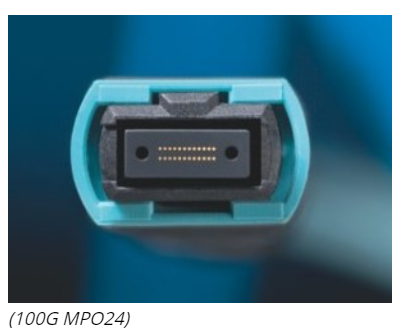
MPO24 Cabling is for 100G SR10 connections used primarily for CXP HPC clusters. There are 24 separate fibers which makes the cable some what more expensive to manufacture. This kind of cable is fairly rare to find and the 100G SR10 standard will slowly fade and be replaced with 100G SR4. Would be a seriously bad idea to invest anything into this format.
MPO12 SHORT REACH 100G SR4 - THE WINNER
For 100G Short reach MPO12 cabling is the clear winner. Its identical to 40G SR4 connector and cabling, so while an all out 100G everything budget might be a little large, you can upgrade cabling and patch panels to 40G MPO12. And when the 100G pricing comes down all that's required is updating the optics to 100G - if you bought a dual mode 40G/100G switch.

100G PROTOCOLS
The protocols for 100G are some what less clear. The contenders are SR10, LR10, SR4, LR4, SR4 FEC, LR4 FEC, it can be some what confusing. In the end all of these protocols provide ingress/egress ethernet ports with a data rate of 100.00Gbps and packet rate of 148.88Mpps. (Its surreal if not scary we`re now dealing with 148,888,000 packets per second!)
There`s alot of difference is how each protocol is encoded and what the final bits down the pipe actually look like. Lets dig into the different protocols at a high level.
10 LANES OF 10G
Using 10 lanes of 10G is the easiest way to achieve a 100Gbps link. The first thing to be clear is, 100G LR10/SR10 != 10 x 10G LAG link. The protocol is significantly different.

Above is how a LAG is typically setup. It`s essentially bonding N links into a single virtual port between the switch`s. Transport wise its running over standard 10GBASER SR/LR ethernet but logically its a virtual 100G port. In this case its round-robbin scheduling packets in their entirely down each link. The problem with this is the packets on the receiving end can arrive out of order. Imagine a 1500B packet in Lane0, and a 64B packet in Lane1. The last byte of the 64B packet will arrive before the last byte of the 1500B packet. The LAG protocol has ways to resolve this but in general when we talk about 100G it does not mean 10x10G LAG links.
Next we have true 100G SR10 / LR10 interfaces. From the diagram below it should be clear that 100G SR10 != 10 x 10G SR LAG links.

As you can see in the above picture packets are striped across all the lanes, specifically in 64b/66b chunks so there is no ordering problems. The 100G protocol includes lane deskew via alignment markers, this means the receiving end can precisely align the bits before the packet is reassembled and sent out the MAC. It also includes the BIP8 protocol which provides error detection (but no correction) built into the protocol.
4 LANES OF 25G

Next we have SR4/LR4. Thats 4 lanes of 25G each, or more precisely 4 x 25.78125Ghz due to encoding overhead. It also stripes packets into 64b/66b blocks before sending over all links and includes BIP8 error detection (note: error detection not correction). However there is a twist, there`s actually 2 different standards for 4x25G links. IEEE 802.3 ba and IEEE 802.3 bm.
4 LANES OF 25G + FEC

And finally 100G QSFP28 4x25G+FEC which the industry is converging on. The difference between 802.3ba and 802.3bm is FEC (Forward Error Correction) which changes the stripe size from 64b to 256b and adds a Reed-Solomon error correction parity block. Its very similar to how ECC RAM operates, uses the same math but with slightly different parameters. Think of it as an ECC serial link. So with 802.3bm the receiver can not only detect bit errors, but also correct bit errors and improve the quality of the link substantially.
SUMMARY
In our opinion QSFP28 SR4/LR4 with FEC will become the dominant 100G standard. All switch vendors support FEC and while not mandatory for shorter length SR4 or LR4 we believe FEC will be enabled by default on all 100G links. QSFP28 optics are progressing in availability and pricing with switch vendors heading towards single port multi mode 40G/56G/100G QSFP/QSFP28 physical cages.
Net result is:

Fragmentation in 100G ethernet is finally starting to converge. Its taken a number of years to get here and all that`s remaining is to get the costs down so everyone can enjoy their 100Gbps networks at reasonable prices.
Next we`ll dig deep into the 100G SR4/LR4+FEC standard and explain in detail how it all works.