NETWORK ARCHITECTURE TO CAPTURE PACKETS
Packet capture is good and all, but how exactly do you capture packets on a network ? There`s a range of approaches from Layer1 optical TAP`s to Smart SPAN protocols and everything in between. We dig into the various Pro`s and Con`s of each approach.

NETWORK TOPOLOGY FOR PACKET CAPTURE
Packet capture is great, but how do you actually setup your network topology to get the packets into 10G, 40G or 100G packet sniffer appliance? Turns out there's about 5 different options all with their various pros and cons.
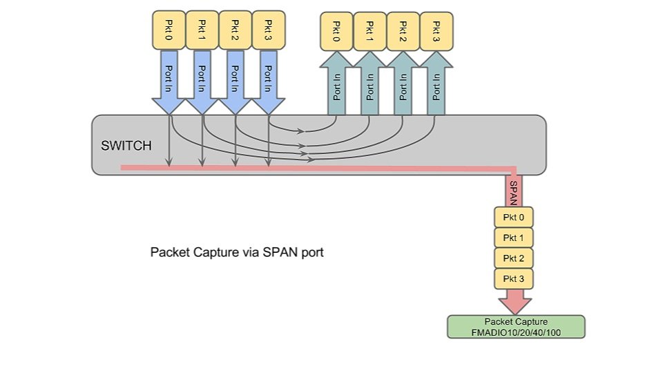
SWITCH SPAN / MIRROR PORT
This is probably the easiest way to get packet capture up and running. It requires the switch to be configured in whats called port "SPAN" or "MIRROR" mode depending on the switch vendors terminology. The idea is simple, make a copy of all ingress packets from Port 0, 1, 2, ... N and forward it to the SPAN port in addition to forwarding the packet to the correct output port. Its simple to setup, does not require any new hardware. Network topology shown in in the picture below.
Pros:
|
Cons:
|
Its a good basic way to to start packet capture, but it will impact your network performance and the time stamp resolution is not great. This is best used on edge switch`s for Security / IDS packet analysis workloads.
INLINE PACKET CAPTURE
Inline packet capture is even simpler to setup but has a major downside, if the packet capture device becomes inactive (e.g. during a system reboot) the entire link goes down. This is a major problem if the link your capturing requires high uptime, as even 1 minute downtime for a system reboot or power cycle can have a large impact on the entire network. The other problem with this approach is it introduces latency and jitter onto the link. How much jitter and latency could be 10`s of nanoseconds, or could be 10`s of milliseconds depending on what hardware you are using.

Pros:
|
Cons:
|

Pros:
|
Cons:
|
This is the recommended way to capture all packets for high uptime links. The only problem, cabling can get a bit messy. The only negative to using this approach is if the optics/transceivers are extremely expensive, e.g. 100G LR4 links. In such case the End point and the Packet capture device require the same transceiver's, which for 100G LR4 adds significant cost ($10K+ USD+ for 100G LR4 in 2015). If using SPAN or Inline you only need one LR4 transceiver's, as the local port can use SR.
However, for latency sensitive analysis, Layer 1 TAP`s are the only way to go. It gives you the best accuracy and has zero impact on the real link, the best of both worlds.
LAYER 1 TAP + SWITCH PACKET CAPTURE
One of the problems with Layer 1 TAP`s is it scales poorly. For one TAP you need 2x 10G capture ports (Rx & Tx lines) so if you have 16 10G duplex lines to tap, it results in 32 10G Rx only ports. If your packet capture device can do 2 x 10G ports it translates to purchasing 16 packet sniffers. Even for our 1U 10G packet sniffer that's a size-able percentage of an entire rack!
Thus enter the aggregation layer. The idea is using a switch or a dedicated 10G aggregation switch you can plug in all the TAP ports into a switch, and then SPAN the aggregated data to the packet capture device, as shown in the diagram below

Pros:
|
Cons:
|
This setup is good, as its completely de-coupled from the real network due to all the passive TAP`s. However things get murky at the aggregation layer. If your using regular run of the mill 10G switch the timing accuracy is quite franky going to suck - the span port will suffer from queuing delays. If its a fancy cut-through switch the accuracy will be better but any packet that requires queuing (e.g. packets arriving from the tap at the same time) will have 100`s of nanoseconds of timing error.
The problem when using a switch and SPAN port is the packet`s time stamp is set by the packet sniffer (highlighted in Red), which is behind the Nx1 MUX. Thus for the ultimate passive network packet capture timing accuracy we need a different plan.
LAYER 1 TAP + FANCY SPAN PACKET CAPTURE
... and finally we arrive at the ultimate network capture setup, using an array of layer 1 TAP`s, fancy pants SPAN session and a 10G line rate packet sniffer. This is for applications that require ultimate time accuracy, meaning +/- 10 nanoseconds.
The setup is almost the same as the above, except using ingress switch time stamping "fancy pants SPAN" sessions. This is available with the latest Arista (EOS span) and Cisco (ER span) protocols. The key difference is the Fancy SPAN adds meta-data to the packet as it transits though the switch and you guessed it, that includes a hardware timestamp when the packet was first received on the switch ingress port not egress (highlighted in red). Resulting in the packet capture device timestamps being replaced by the metadata timestamp the aggregation switch added to the packet.

Pros:
|
Cons:
|
This is the best money can buy right now and its pretty dam good too. Zero network impact and real 1 nsec accurate timestamps. There`s similar alternatives for timestamp aggregation from VSS / Gigamon / MetaMako / Exablaze / and others, these are dedicated to aggregation and time stamping but the price differential is not that different to a switch.. so better off getting a real switch.
Some aggregation switch vendor info.
Cisco ER Span
Cisco ERSPAN RFC
Arista EOS Time stamp
Arista EOS Time stamp FAQ
SUMMARY
Packet capture is never a stand alone system, it only works when embedded in a well designed and deployed network architecture. I hope this gives you some ideas on how to architect your network for maximum cost efficiency or maximum time precision.
If there`s an approach to sourcing packets we have left out please contact us!